- Introduction
- What Is Signal Integrity Testing?
- Basics of Measuring Signal Integrity in a Digital System
- On-Chip Signal Integrity
- Chip-to-Chip Signal Integrity
- How To Determine Oscilloscope Signal Integrity
- When Should You Worry About Signal Integrity?
- How To Improve Signal Integrity
- Simultaneous Switching Noise (Ground Bounce)
- FAQ Regarding Signal Integrity
- Keysight Oscilloscopes
- Popular Used Oscilloscopes
What Is Signal Integrity?
Signal integrity is a measure of the quality of an electrical signal. It is a critical factor in the design of electronic systems and components, particularly high-speed digital devices. Poor signal integrity can lead to errors in data transmission, reduced performance, and
even hardware failures.
Many factors can affect signal integrity, including electromagnetic interference (EMI), crosstalk, impedance mismatches, and signal attenuation. Good design practices and proper testing can help ensure that a system meets its signal integrity requirements
What Is Signal Integrity Testing?
Integrity testing verifies and characterizes the quality of electrical signals in a system. It is an integral part of the design and validation of electronic devices, especially those that operate at high speeds.
There are many integrity tests, each targeting a specific aspect of signal quality. Standard tests include eye diagrams, jitter measurements, and bit error rate (BER) testing.

Basics of Measuring Signal Integrity in a Digital System
There are a number of basic parameters that need to be measured to assess the signal integrity of a digital system.
- Jitter measurements. Jitter is a measure of the variability in the timing of digital signals. It depends on several factors, including noise, crosstalk, and impedance mismatches.
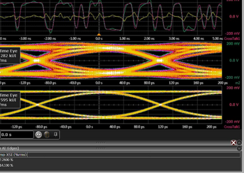
- Eye diagram. An eye diagram is a graphical representation of a digital signal. It shows the signal's voltage level over time and can be used to assess random jitter.
- Bit error rate (BER). The BER measures the percentage of bits received incorrectly. A high BER indicates poor signal integrity.
These are just a few of the more important parameters to be measured when assessing the integrity of a signal. Other factors include noise, crosstalk, and impedance mismatches.

On-Chip Signal Integrity
This testing is a growing area of focus, as the increasing complexity of modern integrated circuits makes it difficult to test them using traditional methods. On-chip signal integrity testing can be performed using specialized hardware and software or by embedding test circuitry within the integrated circuit.
Chip-to-Chip Signal Integrity
This type of testing focuses on the quality of signals passed between two or more integrated circuits. It is often performed using test boards that connect the chip devices. This is a benefit over on-chip testing, as it allows for more realistic signal paths to be used.
How To Determine Oscilloscope Signal Integrity
Several factors need to be considered when determining the signal integrity of an oscilloscope. Some of the most important are the following.
| Factor | Explanation |
|---|---|
| Bandwidth | The bandwidth of an oscilloscope is one of the most important specs to consider when evaluating the integrity of a signal. A scope with a wide bandwidth will be able to capture high-frequency signals with greater fidelity than a scope with a narrower bandwidth. |
| Sample rate | The sample rate of an oscilloscope determines how often the scope measures the signal. A higher sample rate will allow higher measurement resolution of high-speed signals but requires more processing power and memory. |
| Rise time | The rise time of an oscilloscope measures the speed at which the scope can transition from low to high voltage levels. A scope with a fast rise time will be able to capture sharp changes in signal level with greater accuracy than a scope with a slower rise time. |
| Signal-to-noise ratio | The signal-to-noise ratio (SNR) measures the quality of the scope's input stage. A higher SNR means less noise in the signal, and the scope will be able to reproduce the shape of the waveform accurately. |
| Jitter | Jitter is a measure of the stability of the timing of the scope's signals. A scope with low jitter will be able to capture repetitive signals with greater fidelity than a scope with high jitter. |
These are just a few specs that need to be considered when evaluating the integrity of a signal. Other important factors include input impedance, frequency response, and phase noise.
When Should You Worry About Signal Integrity?
There are a few situations where the integrity of a signal becomes a concern:
- High-speed digital systems. Data rates above 1 Gbps require special attention regarding signal integrity.
- RF systems. Signal integrity is especially important in radiofrequency (RF) systems, as even small amounts of interference can cause problems.
- Analog systems. Although signal integrity is less of a concern in analog systems than in digital systems, it can still be a factor in some cases.
If you are designing or working with any of these systems, it is good to be aware of the potential signal integrity issues.
How To Improve Signal Integrity
There are a few basic steps to improve the integrity of a system's signal:
- Use high-quality components. Using high-quality components can help to decrease noise and interference.
- Keep traces short. Traces should be as short as possible to minimize impedance mismatches.
- Minimize crosstalk. Crosstalk can be minimized by keeping traces separated and using shielded cables.
By following these simple guidelines, you can help to ensure that your system has good signal integrity.
Simultaneous Switching Noise (Ground Bounce)
Simultaneous switching noise (ground bounce) is interference that can occur when multiple digital output drivers are switched on and off simultaneously. It is caused by the inductance of the power supply and ground planes and can be minimized using proper grounding techniques and the use of resistors between each of the outputs. Grounding techniques include using a star ground, keeping traces short, and using power and ground planes.
FAQ Regarding Signal Integrity
What Are ADC Bits and ENOB?
The ADC bits are the number of bits an analog-to-digital converter (ADC) uses to quantize an input signal. The greater the number of bits, the more accurate the conversion is. The ENOB (effective number of bits) measures the accuracy of an ADC. It takes into account factors such as noise and distortion that can reduce the accuracy of the conversion.
What Are Impedance and Routing?
Impedance is a measure of the opposition to the flow of an electric current. It is represented by the letter "Z" and is measured in ohms.
Routing is the process of designing the path that traces will take on a circuit board. It is important to consider impedance when routing, as impedance mismatches can cause signal reflections and degrade the integrity of a signal.
What Is Electromagnetic Interference? (EMI)
Electromagnetic interference (EMI) is a type of interference that can degrade the performance of electronic equipment. It is caused by electromagnetic fields and can be minimized using shielding and proper grounding techniques.

Keysight Oscilloscopes
When you're in the market for an oscilloscope, you want one that will give you accurate and reliable measurements every time. That means getting an oscilloscope that has good signal integrity. Keysight is a leading provider of premium market oscilloscopes known for their excellent signal integrity. See Keysights Used Equipment to find a wide range of oscilloscopes to fit your needs.
Popular Used Oscilloscopes
Keysight Used Oscilloscopes offers a wide range of industry leading pre-owened oscilloscopes, ranging from older generation Agilent oscilloscopes to the newest Keysight oscilloscope models. So whether you are a fist time buyer, replacing a model like-for-like or looking for upgrade – we have something for you.


