- Introduction
- What Is Waveform and Signal Analysis?
- Square and Rectangular Waves
- Sine waves
- Triangle Waves
- Sample Rate and Memory
- The Oscilloscope's Graph
- Can Your Oscilloscope Capture Elusive Events?
- How Does an Oscilloscope Measure PWM Signal?
- How Does an Oscilloscope Measure a Sound Signal?
- How To Use an Oscilloscope To Measure Voltage
- How Does an Oscilloscope Measure Negative Signals?
- Why Does Clipping in an Oscilloscope Happen?
- Oscilloscope Signal Advantages vs. Disadvantages
- Keysight Oscilloscopes
- Popular Used Oscilloscopes
What Is an Oscilloscope Signal?
An oscilloscope signal is a voltage signal that varies over time. A digital storage oscilloscope, or DSO for short, displays these signals as waveforms and saves them, which makes it easy to analyse voltage changes. By looking at the waveform, you can quickly see if there are any problems with the signal. For example, if the waveform is not smooth, it may indicate noise in the electrical signal. By looking at the waveform, you can also see if the signal is periodic, which can be helpful in troubleshooting.
What Is Waveform and Signal Analysis?
Waveform and signal analysis is the process of analyzing a waveform to extract underlying information from the signal. This can be done manually by looking at the waveform and trying to identify features or by using specialized software that can automatically analyze the waveform.
By analyzing the waveform, you can extract information about the signal's frequency, amplitude, and other characteristics. This information can help in troubleshooting problems with the input signal or design filters and other circuits that can process the signal.

Square and Rectangular Waves
Two common digital waveforms you will see on an oscilloscope are the square wave and rectangular wave.
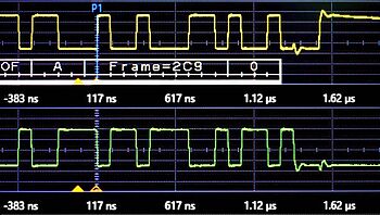
- Square waves are produced by digital circuits, and they have a very distinct shape: the voltage is either high or low, with sharp transitions in between. The width of the high and low parts of the waveform is called the duty cycle. Square waves can have duty cycles of 50%. A 50% duty cycle square wave is sometimes called a clock signal because it looks like a clock ticking.
- Rectangular waves are similar to square waves but the high and low intervals are of different lengths. This makes them look like rectangles instead of squares. Rectangular waves are also produced by digital circuits, and they can have duty cycles that are anywhere from 0% to 100%, which means they can look like clock signals too. The main difference between rectangular and square waves is the irregularities in signal shape.

Sine waves
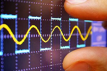
Another common waveform that you will see on an oscilloscope is the sine wave. Sine waves are produced by alternating current (AC) circuits, and they have a very smooth, sinusoidal shape. The amplitude of a sine wave is the maximum height of the waveform, and the wavelength is the distance between two successive peaks of the waveform. Sine waves are often used as a reference signal because they are very easy to generate and allow for precision measurements.

Triangle Waves
Triangle waves are similar to sine waves in that they have discrete maximums and minimums but have a triangular shape instead of a sinusoidal shape. Triangle waves are also produced by AC circuits, and they can have positive or negative slopes, or both. The amplitude of a triangle wave is the maximum height of the waveform, and the wavelength is the distance between two successive peaks of the waveform.
Sample Rate and Memory
When using an oscilloscope, two important factors determining the quality of the waveform you see on the screen are sampling rate and memory depth.
- The sample rate is how often the oscilloscope takes a measurement of the voltage, usually given in samples per second (samples/s).
- The memory depth is how many samples the oscilloscope can store, usually given in number of samples. The combination of a high sample rate and a deep memory depth will give you a high-quality waveform that you can zoom in on and analyze in detail.
The Oscilloscope's Graph
The oscilloscope's graph is made up of two parts, the X-axis, and the Y-axis.
- The X-axis represents time, usually in seconds
- The Y-axis represents amplitude, usually in Volts
The origin of the graph, where the X-axis and Y-axis meet, is called the trigger point. The trigger point is where the oscilloscope starts measuring the voltage and drawing the waveform.
When using a digital oscilloscope, you can set the trigger point to anywhere on the graph. The trigger point is useful for aligning the waveform so you can see specific features more clearly. For example, if you want to measure the width of a pulse, you can set the trigger point to the leading edge of the pulse and then measure from there. This is helpful as it allows you to stabilize repetitive waveforms so that you can take accurate measurements.

Can Your Oscilloscope Capture Elusive Events?
Another important thing to consider when you are using an oscilloscope is whether or not it can capture elusive events. Elusive events are small, transient events that can be hard to see on a waveform. They can be caused by:
- Noise or interference
- Glitches
- Problems with the signal
To capture elusive events, you need an oscilloscope with a high sample rate and a deep memory depth. Otherwise, you might not be able to see the event at all, or you might only see a portion of it.
How Does an Oscilloscope Measure PWM Signal?
Pulse width modulation (PWM) is a digital signal often used to control electrical devices such as motors and LEDs. PWM signals have a duty cycle, which is the “on” pulse width divided by the signal's period. For example, if a PWM signal has a duty cycle of 50%, that means that the width of the “on” pulse is 50% of the period.
Digital scopes can measure PWM signals by measuring the width of the pulse and the duty cycle. To do this, you need to set the trigger point to the leading edge of the pulse and then measure from there. You can also use the oscilloscope's maths functions to calculate the duty cycle.
How Does an Oscilloscope Measure a Sound Signal?
Sound is a type of analog signal that is often measured with an oscilloscope. To measure a sound signal, you need to connect the sound source to the scope input. The sound source can be anything that produces sound, such as a microphone, an audio player, or a speaker.
The oscilloscope will measure the amplitude of the sound signal and display it as a waveform. The amplitude is the height of the waveform, and it is usually given in volts (V). The higher the amplitude, the louder the sound. You can use the oscilloscope to measure the peak amplitude of the sound signal, or you can use the RMS amplitude, which is a measure of the average amplitude.
You can also use the oscilloscope to measure the sound signal over a range of frequencies. The frequency is the number of times the waveform repeats itself in one second and is usually given in hertz (Hz). The higher the frequency noise, the higher the pitch of the sound.
How To Use an Oscilloscope To Measure Voltage
Voltage is the difference in electric potential between two points and is usually measured in Volts (V). To measure voltage with an oscilloscope, you need to connect the two points to the oscilloscope's input. The two points can be any two conductors, such as wires or electrical components.
The oscilloscope will measure the signal voltage between the two points and display it as a waveform. The amplitude of the waveform will be the voltage, which will be given in volts (V).
How Does an Oscilloscope Measure Negative Signals?
Negative voltage signals are voltages that are below zero volts. Negative voltages can be generated by batteries, solar cells, and other sources. Negative voltages can also be created by inverting positive voltages with an electronic device called an inverter.
An oscilloscope can measure negative voltage signals by connecting the two points to the scope's input. The scope will then measure the signal voltage between the two points and display it as a waveform. If the voltage is negative, the waveform will be inverted, and the voltage will be given as a negative number. For example, if the voltage is -5 V, the waveform is 5 V below zero.
Why Does Clipping in an Oscilloscope Happen?
Clipping happens when the amplitude of a signal exceeds the limits of the oscilloscope's input. The oscilloscope will clip the signal at the maximum level it can measure, distorting the waveform. Clipping can be caused by an electrical fault, such as a short circuit, or by connecting the oscilloscope to a signal that is too large.
Oscilloscope Signal Advantages vs. Disadvantages
| Advantages | Disadvantages |
|---|---|
| Signals are easy to generate | Can be distorted by clipping |
| Can be measured with a wide range of instruments | Difficult to interpret if the waveform is not well-defined |
| Signals are usually stable and suitable to use for calibration and testing | Susceptible to noise and interference |
| Signals can be recorded and played back | Difficult to troubleshoot if there is a problem with the waveform |
Keysight Oscilloscopes
As we have looked at, digital oscilloscopes are used to measure all sorts of signals, from DC voltages to audio signals. In this article, we've looked at some of the most common signals measured with an oscilloscope. We've also seen how to connect the oscilloscope to the signal source and interpret the waveform displayed on the screen. Understanding these basics can help you know what you need in an oscilloscope. See all Keysight Used Equipment and find the right oscilloscope to fit your needs.
Popular Used Oscilloscopes
Keysight Used Oscilloscopes offers a wide range of industry leading pre-owened oscilloscopes, ranging from older generation Agilent oscilloscopes to the newest Keysight oscilloscope models. So whether you are a fist time buyer, replacing a model like-for-like or looking for upgrade – we have something for you.


